
How to 3D print an Ion Mobility Spectrometer
- goodgreenlife

- 6 days ago
- 6 min read
Updated: 6 days ago
The aim of this guide is to explain how to make a 3D ion mobility spectrometer for the beginner i.e. myself using the paper written by Sebastian Brandt and others at ISAS in Germany (link). Supposedly it should take a user 1 day and 9 hours to make a DTIMS (Drift tube Ion mobility spectrometer) when you have all the relevant materials and machinery on hand. According to the author, the fundamental principle is that every functional IMS component should be independently printable, testable and replaceable. I look forward to trying this when I have stable accommodation.
Finding guides on how to make a mass spectrometer has been considerably difficult and something I am actively looking into. Note there has been a more recently published paper (April 2024) by him on manufacturing of drift tubes using additive manufacturing with coaxial filament (link). In addition there’s also an article on Flexible Drift tube for High Resolution Ion Mobility Spectrometry (Flex-DT-IMS) by Simon Maher and others worth reading (link). As well as another guide for a print in place IMS by Hauck (link). But for now, I’ll keep it simple and to one paper.
Core System Architecture
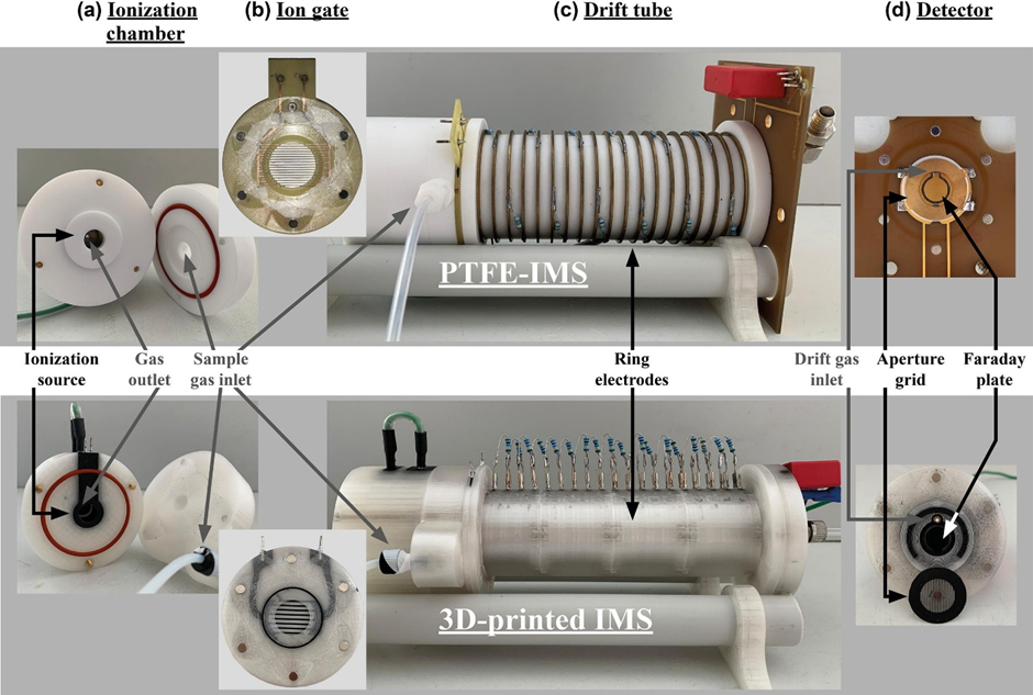
The instrument consists of 5 main functional modules all designed to be printed separately
1. Ionisation chamber
2. Bradbury-Nielson gate
3. Drift tube with field electrodes
4. Detector (aperture grid + Faraday plate)
5. Modular housing + magnetic connectors
Bradbury-Neilson is an electrical ion gate used as an electron filter. Faraday plate or an electron multiplier convert the ions into current, which allows for their quantification.

Parts List
3D Printing Equipment
Ultimaker 3 (or similar dual-extrusion FDM 3D printer)
Ultimaker 2 (or printer with interchangeable nozzles for fine details)
Nozzles: 0.4mm ID (×2), 0.25mm ID (×1), 0.1mm ID (×1)
Printing Materials
Non-conductive PLA (clear) - EasyFil PLA or equivalent (~500g)
Conductive PLA (black) - Proto-Pasta Electrically Conductive Composite PLA (~300g)
Electronic Components
Ionization source: ⁶³Ni β-radiator (550 MBq) - Requires regulatory approval and licensing
High voltage power supply: 5 kV output
Resistors: 19× 1 MΩ resistors (for drift tube electrode cascade)
Solder pins: ~30 pieces for electrical connections
BNC connector: 1× (Amphenol RF or equivalent)
Data acquisition board: Custom or commercial IMS controller
Control unit: For gate timing and signal processing
Hardware & Fasteners
Neodymium magnets: 4×2mm, 450g magnetic force (~24 pieces)
Sealing rings (O-rings):
40×2mm MVQ 30 (×1)
24×1mm MVQ 55 (×1)
22×1.5mm MVQ 50 (×1)
15×2mm MVQ 40 (×4)
Screws: Assorted small screws for ionization chamber assembly
Gas Handling
Nitrogen gas (purity 6.0 or higher)
Gas flow controller: For 300 mL/min drift gas flow
Tubing and fittings: For gas connections
Software
· CAD software: Autodesk Inventor Professional (or FreeCAD, Fusion 360)
· Slicing software: Cura 4.4.1 or later
· G-code editor: Repetier Host 2.1.6 (for fine detail work)
· Data analysis: Custom software or OriginPro for spectrum analysis
Construction Guide
Step 1: Design Preparation
Create or download CAD files for all IMS components:
Ionization chamber (2 parts)
Bradbury-Nielsen gate mounting
Drift tube (4 parts: 2 flanges, electrode section, housing)
Detector assembly
Export designs as STL files from your CAD software
Configure slicing software with these base settings:
Layer height: 0.1mm
Wall thickness: 1.6mm
Conductive PLA: 220°C nozzle, 100% infill, concentric pattern
Non-conductive PLA: 205°C nozzle, 30% infill
Build plate: 60°C constant
Print speed: 70mm/s
Step 2: Print the Ionization Chamber
Components: Sample inlet system + ionization region with electrodes
Ionization Region:
Load conductive PLA (black) in left nozzle, non-conductive PLA (clear) in right nozzle
Print using dual extrusion mode
The design embeds a ring electrode and cylindrical electrode (conductive) within an insulating housing (non-conductive)
Print time: ~8-12 hours
Sample Inlet:
Print using non-conductive PLA only
Print time: ~4-6 hours
Assembly:
Insert six 4×2mm neodymium magnets into designated cavities in the ionization chamber
Install 40×2mm sealing ring
Insert ⁶³Ni β-radiator into cylindrical electrode (follow all radiation safety protocols)
Connect electrodes with wire and secure with screws
Attach sample inlet to ionization region
Step 3: Print the Bradbury-Nielsen Gate
This requires precision printing with fine nozzles

Recommended Design (Ion Gate 3):
Grid linewidth: 0.15mm
Grid line spacing: 0.25mm
Uses 0.1mm nozzle
Printing Process:
Create custom G-code using Repetier Host for ultra-fine grid lines
Print grid lines (conductive PLA) directly onto glass build plate first
Print two sets of interleaved parallel wires
Add two-layer frame (non-conductive PLA) on top
Print time: ~2-3 hours
Handle with extreme care - structures are delicate
Gate Mounting:
Print mounting bracket with dual extrusion
Insert solder pins for electrical contacts
Embed magnets for modular connection
Install 22×1.5mm sealing ring
Carefully place printed gate into mounting with press ring
Step 4: Print the Drift Tube (Optimized Design - Drift Tube 2)
Components: 2 flanges + electrode section + insulating housing
Key Design Features:
19 ring electrodes with reduced insulation thickness (0.8mm)
Inner diameter: 15.2mm
Outer diameter: 39mm
Length: 12cm
Printing Process:
Print electrode section with conductive PLA:
19 stacked ring electrodes
Minimum 2mm thickness, 100% infill
Print time: ~12-16 hours
Print insulating housing with non-conductive PLA:
Thin walls (0.8mm) between electrodes and drift region
Print time: ~10-12 hours
Print two flanges with dual extrusion:
Embed magnets in both flanges
Install 15×2mm sealing rings
Print time: ~4-6 hours each
Assembly:
Insert 19 solder pins into electrode contact points
Connect electrodes with 1 MΩ resistors in series (creates voltage cascade)
Assemble electrode section into housing
Attach flanges to both ends with sealing rings
Verify all electrical connections
Step 5: Print the Detector
Components: Faraday plate + aperture grid + housing
Aperture Grid:
Use 0.1mm nozzle with conductive PLA
Print outer conductive frame first
Add grid lines (~100μm linewidth)
Print time: ~2-3 hours
Detector Body:
Use dual extrusion mode
Print with electrodes facing build plate for smoothest surface
Design includes three concentric structures:
Inner Faraday plate (conductive)
Ground shield ring (conductive)
Outer connector ring (conductive)
All embedded in non-conductive housing
Print time: ~6-8 hours
Assembly:
Press BNC connector into housing
Insert solder pins for connections
Install 24×1mm sealing ring
Embed magnets for modular connection
Mount aperture grid with drift gas inlet between grid and Faraday plate
Step 6: System Integration
Electrical Connections:
High voltage cascade: Connect drift tube resistors from ionization chamber (5kV) down to detector (ground)
Gate control: Connect Bradbury-Nielsen gate wires to control unit
Signal detection: Connect Faraday plate to data acquisition board via BNC connector
Ground connections: Ensure proper grounding throughout
Gas System:
Connect nitrogen supply to drift gas inlet at detector
Set flow rate to 300 mL/min
Connect sample inlet for analyte introduction
Connect gas outlet from ionization chamber
Modular Assembly:
Align ionization chamber to gate mounting using magnets
Attach gate mounting to drift tube flange using magnets
Connect drift tube to detector using magnets
Verify all sealing rings are properly seated
Step 7: Initial Testing & Calibration
Running-In Period:
Power on system with drift gas flowing
Allow 24-hour stabilization period for drift time equilibrium
Monitor reactant ion peak (RIP) position and intensity
Gate Timing:
Set ion gate opening time: 300μs
Set repetition cycle: 50ms
Adjust as needed for your application
Performance Verification:
Measure RIP characteristics:
Drift time should stabilize at ~16.7ms (with nitrogen drift gas)
Signal intensity should be stable
Peak width (FWHM) ~0.38-0.50ms
Test with calibration standards (e.g., ketone isomers)
Calculate resolving power: should achieve 40-50
Measure signal-to-noise ratio: target >200

Safety Warnings
⚠️ CRITICAL SAFETY REQUIREMENTS:
Radioactive Material: The ⁶³Ni source requires:
Proper licensing and regulatory approval
Radiation safety training
Appropriate shielding and handling procedures
Compliance with local radiation safety regulations
High Voltage: 5kV system requires:
Proper electrical safety training
Insulated tools and work area
Emergency shutoff accessible
No work on live circuits
Compressed Gas:
Proper gas cylinder handling and storage
Appropriate regulators and pressure relief
Adequate ventilation
Troubleshooting
Problem: Drift time shifts over time Solution: Ensure insulating layer in drift tube is ≤0.8mm thick. May require 60+ hour stabilization with thicker designs.
Problem: Low signal intensity Solution: Check electrode connections, verify gas flow rates, consider activating 3D-printed Faraday plate surface.
Problem: Poor peak resolution Solution: Verify gate timing (300μs), check for gas leaks at sealing rings, ensure uniform electric field in drift tube.
Problem: Gate not closing properly Solution: Verify voltage levels on gate wires, check for wire damage, ensure proper gate mounting alignment.
Performance Expectations
With this optimized design, you should achieve:
Resolving power: 40-50
Signal-to-noise ratio: 220-250
Resolution (for isomers): 1.4-1.8
Drift time stability: Within 0.3ms of commercial systems
Running-in time: ~24 hours
Cost & Time Estimates
Total printing time: ~60-80 hours Material cost: ~$150-200 (filaments only) Electronics cost: $500-2000 (depending on components chosen and country you are in) Total project time: 2-3 weeks including printing, assembly, and calibration
For details on what to print please see Supplementary data (link)


Comments